Monday, 16 October 2017
PDC172 takes to the Air
After three years of work - often with long breaks in between progress - PDC 172 has taken to the air with surround scenery and flight instruments. It's now in a state where it has become very flyable, but there's still lots to do to get everything, including the visuals, properly configured - I'm pretty happy with this progress 😊. Here's a circuit at Christchurch International - not the best of landings, but not bad after 3 years without a flight fix 😉
Friday, 22 September 2017
Using Warping Software on Surround Scenery and Other Monitors
OK, this is the dilemma I had with setting up surround screen scenery and using the remaining ports on the graphics card for the instruments in the cockpit.
When you're projecting onto a curved screen you need to use warping software. I found out that with the graphics card I'm using - the GeForce GTX 980 - you can enable a surround option. This effectively joins two or more monitors or projectors together to form a continuous image. This then enabled me to use the warping software (Nthusim) across the whole screen. The diagram below shows my original thinking on the setup.
However, as soon as I turned on the surround option I lost the use of the remaining ports on the graphics card. Disabling the surround option gave me back the other ports, but then prevented the warping software from working - it only appeared on one screen.
It took a lot of research; this included looking at a number of YouTube videos on extending your desktop whilst having surround scenery. These suggested using two graphics cards (assuming your system allows this). Further investigation, including an on-line chat with Nvidia suggested the only way was to use two SLI (Scalable Link Interface) cards......by this time I had already bought a second card - the GeForce GTX 1050ti (not SLI compatible). I was a bit gutted thinking I had wasted quite a few dollars!!
I took the card back to PB Tech where I spoke with Karl, a very helpful support and service technician. After about 20 minutes of discussion and looking on line, we agreed I would try the card. This diagram shows the configuration of two cards in the one machine - not using SLI.
When you're projecting onto a curved screen you need to use warping software. I found out that with the graphics card I'm using - the GeForce GTX 980 - you can enable a surround option. This effectively joins two or more monitors or projectors together to form a continuous image. This then enabled me to use the warping software (Nthusim) across the whole screen. The diagram below shows my original thinking on the setup.
 |
| One option was to consider adding another networked computer |
However, as soon as I turned on the surround option I lost the use of the remaining ports on the graphics card. Disabling the surround option gave me back the other ports, but then prevented the warping software from working - it only appeared on one screen.
It took a lot of research; this included looking at a number of YouTube videos on extending your desktop whilst having surround scenery. These suggested using two graphics cards (assuming your system allows this). Further investigation, including an on-line chat with Nvidia suggested the only way was to use two SLI (Scalable Link Interface) cards......by this time I had already bought a second card - the GeForce GTX 1050ti (not SLI compatible). I was a bit gutted thinking I had wasted quite a few dollars!!
I took the card back to PB Tech where I spoke with Karl, a very helpful support and service technician. After about 20 minutes of discussion and looking on line, we agreed I would try the card. This diagram shows the configuration of two cards in the one machine - not using SLI.
 |
| Two GPUs in the one machine - one for surround scenery and one for the instruments |
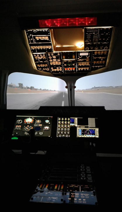
Having set up the second GPU and juggled a bit with the Nvidia software (I'll discuss this in another blog), I'm please to say I now have full screen surround scenery and monitors displaying the flight and engine instruments. This is what it's looking like - still a bit to do to get the images right, but at least they are there.....I'm quite chuffed 😊!
In the end, thanks to Karl in PB Tech and also Marek Marciniak for his YouTube videos on Home FSX cockpit with multiple monitors in Nvidia Surround everything is now connecting the way I want it to as the image below shows - I have since added a third monitor below the flight and engine instruments for flight management etc.


In the end, thanks to Karl in PB Tech and also Marek Marciniak for his YouTube videos on Home FSX cockpit with multiple monitors in Nvidia Surround everything is now connecting the way I want it to as the image below shows - I have since added a third monitor below the flight and engine instruments for flight management etc.

Thursday, 13 July 2017
I Sometimes Wonder about Quality Control!
The other day I was in our local hardware store - 100 km away in Christchurch - and I saw some reasonably priced LED lighting strip designed for domestic use, complete with transformer plug. You can guess where it's made .... a land of great population!
 At home I opened it up an plugged it in - it looked great and would serve my purpose beautifully. My plan, as you may have seen from my last post is to use it as the back lighting for the instrument panel. On unplugging the transformer, I wanted to know a bit more about the rating - voltage, current and power etc so I looked at the underside and found this - scorch marks - how can something brand new have scorch marks on it - suspicions raised!

On further use and examination of the actual strip I found one place where a botched fix to the strip had been made. Looking at it you would have thought this was something I would have done to fix/insulate a cut. The air around me was starting to turn blue about a certain race of people.

By this time I was looking out for the smallest sign of fault and damage and this is the next thing I found.
It's questionable whether this is acceptable or not? LED strip light should come as one long strip that you can choose to cut at various points to meet your need. In this case, it looks quite clear that in the manufacturing process short strips have been joined together to form the 5 m length that I bought. If you look at this photo you can see the solder points where it's been joined - OK, one point throughout the whole length might be acceptable, but I found two of these within about 30 cm of each other. What this means is there are inherent weak points built into the strip right from the start. This is just pure, shoddy, cheap-skate workmanship being passed on to the customer with no evidence of serious quality control. The manufacturer is making a fast buck at the consumer's expense and not to mention the poor soul(s) stuck in some sweat-shop earning a pittance doing the soldering.

What is more important is this is being imported and accepted by our country's trade and industry department.
This is the product I bought - BEWARE!
Frustrations vented!
Sunday, 9 July 2017
Overhead Panel - Finally There. Screen - Finally There
The Overhead Panel and the Screen
I can't believe it's been nearly a year since I last posted, but that just confirms how busy life can be. Work has taken a turn for the better - at school and I've now also become the Team Leader for our local volunteer St John Ambulance team.... which has also brought with it a new set of challenges.
But that's not what this blog is about!
Overhead Panel
I'm quite happy with the results of how this is displaying so far. There's still more to do, but the long work of cutting out the bits that need to be back lit and completing the back lighting has worked well (if you can afford it, commercial printing would be a good option and is something I might do in the future.
 I've had to make compromises with the switches. The BAe 146 had white switches but it's just not been possible to find any at an affordable price so I'm thinking I might paint them myself.
I've used strip LED lighting which was supposed to be self adhering, but that's not worked too well with the tight angles, so I'll be using cable ties to hold the strip in place.
The next challenge will be to start on the electronic interfacing and programming - looking forward to that! There are a couple of software options including Jim's Page and FSUIPC to name but two. I'll probably use both of these and just hope they have the breadth to cope with the vast array needed to make this lot functional.

Here's the overhead panel in it's proper place ....... next step is to start adding functionality to it - that should be fun!!
If your'e thinking of using LED strip lights then you had best read my next post on Quality Control
The Screen
I'm on my third or fourth go at this! every earlier option, in our shaky land (NZ) ended up with cracks. This option involves using calico.....a type of canvas type material that can be bought reasonably inexpensively in large single sheets. In this case I needed a sheet 2.4 m wide by 5 m long. The first challenge was ironing all the creases out and then the second challenge was sticking it up. I uses standard wall paper paste and a staple gun. Having made canvases for painting in the paste I know that you start stretching from the centre and work your way out, so that's what I did. The end result looks pretty good and I'm sure this time I have got the right solu
tion. It's a bit hard to see, but you can judge for yourself from this shot I took of the screen partially painted.
I can't believe it's been nearly a year since I last posted, but that just confirms how busy life can be. Work has taken a turn for the better - at school and I've now also become the Team Leader for our local volunteer St John Ambulance team.... which has also brought with it a new set of challenges.
But that's not what this blog is about!
Overhead Panel
I'm quite happy with the results of how this is displaying so far. There's still more to do, but the long work of cutting out the bits that need to be back lit and completing the back lighting has worked well (if you can afford it, commercial printing would be a good option and is something I might do in the future.

 |
| LED strip lighting for back lighting |
I've used strip LED lighting which was supposed to be self adhering, but that's not worked too well with the tight angles, so I'll be using cable ties to hold the strip in place.
 |
| LED strip coming away from it's fixing point |
The next challenge will be to start on the electronic interfacing and programming - looking forward to that! There are a couple of software options including Jim's Page and FSUIPC to name but two. I'll probably use both of these and just hope they have the breadth to cope with the vast array needed to make this lot functional.

Here's the overhead panel in it's proper place ....... next step is to start adding functionality to it - that should be fun!!
If your'e thinking of using LED strip lights then you had best read my next post on Quality Control
The Screen
I'm on my third or fourth go at this! every earlier option, in our shaky land (NZ) ended up with cracks. This option involves using calico.....a type of canvas type material that can be bought reasonably inexpensively in large single sheets. In this case I needed a sheet 2.4 m wide by 5 m long. The first challenge was ironing all the creases out and then the second challenge was sticking it up. I uses standard wall paper paste and a staple gun. Having made canvases for painting in the paste I know that you start stretching from the centre and work your way out, so that's what I did. The end result looks pretty good and I'm sure this time I have got the right solu
tion. It's a bit hard to see, but you can judge for yourself from this shot I took of the screen partially painted.
 | ||
Semi-circular screen with calico fixed to it and partly painted
|

Subscribe to:
Posts (Atom)