Progress has really slowed on the build of my home-built flight
deck. Partly because work has been so busy and partly because
I’m at the stage where I’m treading new ground and so doing a lot of thinking
before I act.
As you’ve seen in my earlier posts, I’m working on the overhead panel at
the moment and my aim is to make all the switches and dial work as they
should….or at least as closely as I can. Because I’m trying to keep
the cost of the whole project down to the minimum I’ve accepted that I’m not building
an exact replica, but everything will be in its right position at least.
I’ve already written a couple of posts about the instrument panels, but
as I’ve worked and tested so I’ve learnt!
First, cutting Perspex. If you’ve tried working with Perspex
before you know it can shatter very easily if you work with it too
aggressively. The answer is, take it slow and take it gently. By
this I mean when cutting on something like a table saw the n ensure the blade
is set nice and low – only marginally above the thickness of the plastic. Likewise,
if you’re drilling, set the speed to high and, if you’re cutting a large hole,
start by drilling a small hole first and then work up to the large one.
I've refined my process for making the various panels that go into
making up the overhead so; secondly, I've used a table saw to accurately cut
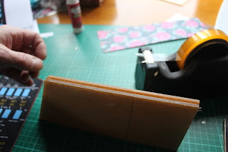
the Perspex to the right size and shape. In this image you can see the
instrument panel and the two matching pieces of Perspex (still with its
protective paper on).
Once the Perspex is taped together I glued a copy of the display the
protective paper of the top copy. This copy is purely used as the guide
to cutting out all the holes for the switches and dials.

I then drilled pilot hole before using a Dremel Moto scroll saw to cut
out the holes for the switches. You may notice I'm not drilling the small
corner holes - I've found that this wasn't necessary and this method is making
the final result so much neater than my early attempts.
Finally, in this picture from left to right, you can see the three
stages:
- drilling the pilot holes
- cutting the holes out with
the scroll saw
- fitting the switches.
In case
you're wondering, I made the displays using Microsoft Publisher


