Monday 16 October 2017
PDC172 takes to the Air
After three years of work - often with long breaks in between progress - PDC 172 has taken to the air with surround scenery and flight instruments. It's now in a state where it has become very flyable, but there's still lots to do to get everything, including the visuals, properly configured - I'm pretty happy with this progress 😊. Here's a circuit at Christchurch International - not the best of landings, but not bad after 3 years without a flight fix 😉
Friday 22 September 2017
Using Warping Software on Surround Scenery and Other Monitors
OK, this is the dilemma I had with setting up surround screen scenery and using the remaining ports on the graphics card for the instruments in the cockpit.
When you're projecting onto a curved screen you need to use warping software. I found out that with the graphics card I'm using - the GeForce GTX 980 - you can enable a surround option. This effectively joins two or more monitors or projectors together to form a continuous image. This then enabled me to use the warping software (Nthusim) across the whole screen. The diagram below shows my original thinking on the setup.
However, as soon as I turned on the surround option I lost the use of the remaining ports on the graphics card. Disabling the surround option gave me back the other ports, but then prevented the warping software from working - it only appeared on one screen.
It took a lot of research; this included looking at a number of YouTube videos on extending your desktop whilst having surround scenery. These suggested using two graphics cards (assuming your system allows this). Further investigation, including an on-line chat with Nvidia suggested the only way was to use two SLI (Scalable Link Interface) cards......by this time I had already bought a second card - the GeForce GTX 1050ti (not SLI compatible). I was a bit gutted thinking I had wasted quite a few dollars!!
I took the card back to PB Tech where I spoke with Karl, a very helpful support and service technician. After about 20 minutes of discussion and looking on line, we agreed I would try the card. This diagram shows the configuration of two cards in the one machine - not using SLI.
When you're projecting onto a curved screen you need to use warping software. I found out that with the graphics card I'm using - the GeForce GTX 980 - you can enable a surround option. This effectively joins two or more monitors or projectors together to form a continuous image. This then enabled me to use the warping software (Nthusim) across the whole screen. The diagram below shows my original thinking on the setup.
 |
| One option was to consider adding another networked computer |
However, as soon as I turned on the surround option I lost the use of the remaining ports on the graphics card. Disabling the surround option gave me back the other ports, but then prevented the warping software from working - it only appeared on one screen.
It took a lot of research; this included looking at a number of YouTube videos on extending your desktop whilst having surround scenery. These suggested using two graphics cards (assuming your system allows this). Further investigation, including an on-line chat with Nvidia suggested the only way was to use two SLI (Scalable Link Interface) cards......by this time I had already bought a second card - the GeForce GTX 1050ti (not SLI compatible). I was a bit gutted thinking I had wasted quite a few dollars!!
I took the card back to PB Tech where I spoke with Karl, a very helpful support and service technician. After about 20 minutes of discussion and looking on line, we agreed I would try the card. This diagram shows the configuration of two cards in the one machine - not using SLI.
 |
| Two GPUs in the one machine - one for surround scenery and one for the instruments |
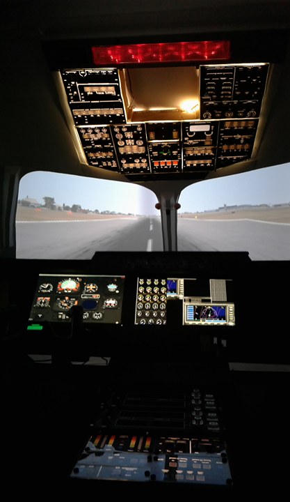
Having set up the second GPU and juggled a bit with the Nvidia software (I'll discuss this in another blog), I'm please to say I now have full screen surround scenery and monitors displaying the flight and engine instruments. This is what it's looking like - still a bit to do to get the images right, but at least they are there.....I'm quite chuffed 😊!
In the end, thanks to Karl in PB Tech and also Marek Marciniak for his YouTube videos on Home FSX cockpit with multiple monitors in Nvidia Surround everything is now connecting the way I want it to as the image below shows - I have since added a third monitor below the flight and engine instruments for flight management etc.


In the end, thanks to Karl in PB Tech and also Marek Marciniak for his YouTube videos on Home FSX cockpit with multiple monitors in Nvidia Surround everything is now connecting the way I want it to as the image below shows - I have since added a third monitor below the flight and engine instruments for flight management etc.

Thursday 13 July 2017
I Sometimes Wonder about Quality Control!
The other day I was in our local hardware store - 100 km away in Christchurch - and I saw some reasonably priced LED lighting strip designed for domestic use, complete with transformer plug. You can guess where it's made .... a land of great population!
 At home I opened it up an plugged it in - it looked great and would serve my purpose beautifully. My plan, as you may have seen from my last post is to use it as the back lighting for the instrument panel. On unplugging the transformer, I wanted to know a bit more about the rating - voltage, current and power etc so I looked at the underside and found this - scorch marks - how can something brand new have scorch marks on it - suspicions raised!

On further use and examination of the actual strip I found one place where a botched fix to the strip had been made. Looking at it you would have thought this was something I would have done to fix/insulate a cut. The air around me was starting to turn blue about a certain race of people.

By this time I was looking out for the smallest sign of fault and damage and this is the next thing I found.
It's questionable whether this is acceptable or not? LED strip light should come as one long strip that you can choose to cut at various points to meet your need. In this case, it looks quite clear that in the manufacturing process short strips have been joined together to form the 5 m length that I bought. If you look at this photo you can see the solder points where it's been joined - OK, one point throughout the whole length might be acceptable, but I found two of these within about 30 cm of each other. What this means is there are inherent weak points built into the strip right from the start. This is just pure, shoddy, cheap-skate workmanship being passed on to the customer with no evidence of serious quality control. The manufacturer is making a fast buck at the consumer's expense and not to mention the poor soul(s) stuck in some sweat-shop earning a pittance doing the soldering.

What is more important is this is being imported and accepted by our country's trade and industry department.
This is the product I bought - BEWARE!
Frustrations vented!
Sunday 9 July 2017
Overhead Panel - Finally There. Screen - Finally There
The Overhead Panel and the Screen
I can't believe it's been nearly a year since I last posted, but that just confirms how busy life can be. Work has taken a turn for the better - at school and I've now also become the Team Leader for our local volunteer St John Ambulance team.... which has also brought with it a new set of challenges.
But that's not what this blog is about!
Overhead Panel
I'm quite happy with the results of how this is displaying so far. There's still more to do, but the long work of cutting out the bits that need to be back lit and completing the back lighting has worked well (if you can afford it, commercial printing would be a good option and is something I might do in the future.
 I've had to make compromises with the switches. The BAe 146 had white switches but it's just not been possible to find any at an affordable price so I'm thinking I might paint them myself.
I've used strip LED lighting which was supposed to be self adhering, but that's not worked too well with the tight angles, so I'll be using cable ties to hold the strip in place.
The next challenge will be to start on the electronic interfacing and programming - looking forward to that! There are a couple of software options including Jim's Page and FSUIPC to name but two. I'll probably use both of these and just hope they have the breadth to cope with the vast array needed to make this lot functional.

Here's the overhead panel in it's proper place ....... next step is to start adding functionality to it - that should be fun!!
If your'e thinking of using LED strip lights then you had best read my next post on Quality Control
The Screen
I'm on my third or fourth go at this! every earlier option, in our shaky land (NZ) ended up with cracks. This option involves using calico.....a type of canvas type material that can be bought reasonably inexpensively in large single sheets. In this case I needed a sheet 2.4 m wide by 5 m long. The first challenge was ironing all the creases out and then the second challenge was sticking it up. I uses standard wall paper paste and a staple gun. Having made canvases for painting in the paste I know that you start stretching from the centre and work your way out, so that's what I did. The end result looks pretty good and I'm sure this time I have got the right solu
tion. It's a bit hard to see, but you can judge for yourself from this shot I took of the screen partially painted.
I can't believe it's been nearly a year since I last posted, but that just confirms how busy life can be. Work has taken a turn for the better - at school and I've now also become the Team Leader for our local volunteer St John Ambulance team.... which has also brought with it a new set of challenges.
But that's not what this blog is about!
Overhead Panel
I'm quite happy with the results of how this is displaying so far. There's still more to do, but the long work of cutting out the bits that need to be back lit and completing the back lighting has worked well (if you can afford it, commercial printing would be a good option and is something I might do in the future.

 |
| LED strip lighting for back lighting |
I've used strip LED lighting which was supposed to be self adhering, but that's not worked too well with the tight angles, so I'll be using cable ties to hold the strip in place.
 |
| LED strip coming away from it's fixing point |
The next challenge will be to start on the electronic interfacing and programming - looking forward to that! There are a couple of software options including Jim's Page and FSUIPC to name but two. I'll probably use both of these and just hope they have the breadth to cope with the vast array needed to make this lot functional.

Here's the overhead panel in it's proper place ....... next step is to start adding functionality to it - that should be fun!!
If your'e thinking of using LED strip lights then you had best read my next post on Quality Control
The Screen
I'm on my third or fourth go at this! every earlier option, in our shaky land (NZ) ended up with cracks. This option involves using calico.....a type of canvas type material that can be bought reasonably inexpensively in large single sheets. In this case I needed a sheet 2.4 m wide by 5 m long. The first challenge was ironing all the creases out and then the second challenge was sticking it up. I uses standard wall paper paste and a staple gun. Having made canvases for painting in the paste I know that you start stretching from the centre and work your way out, so that's what I did. The end result looks pretty good and I'm sure this time I have got the right solu
tion. It's a bit hard to see, but you can judge for yourself from this shot I took of the screen partially painted.
 | ||
Semi-circular screen with calico fixed to it and partly painted
|

Monday 18 July 2016
Instrument Panel – Perfecting the Art!
Progress has really slowed on the build of my home-built flight
deck. Partly because work has been so busy and partly because
I’m at the stage where I’m treading new ground and so doing a lot of thinking
before I act.
As you’ve seen in my earlier posts, I’m working on the overhead panel at
the moment and my aim is to make all the switches and dial work as they
should….or at least as closely as I can. Because I’m trying to keep
the cost of the whole project down to the minimum I’ve accepted that I’m not building
an exact replica, but everything will be in its right position at least.
I’ve already written a couple of posts about the instrument panels, but
as I’ve worked and tested so I’ve learnt!
First, cutting Perspex. If you’ve tried working with Perspex
before you know it can shatter very easily if you work with it too
aggressively. The answer is, take it slow and take it gently. By
this I mean when cutting on something like a table saw the n ensure the blade
is set nice and low – only marginally above the thickness of the plastic. Likewise,
if you’re drilling, set the speed to high and, if you’re cutting a large hole,
start by drilling a small hole first and then work up to the large one.

I've refined my process for making the various panels that go into
making up the overhead so; secondly, I've used a table saw to accurately cut
the Perspex to the right size and shape. In this image you can see the
instrument panel and the two matching pieces of Perspex (still with its
protective paper on).


Once the Perspex is taped together I glued a copy of the display the
protective paper of the top copy. This copy is purely used as the guide
to cutting out all the holes for the switches and dials.

I then drilled pilot hole before using a Dremel Moto scroll saw to cut
out the holes for the switches. You may notice I'm not drilling the small
corner holes - I've found that this wasn't necessary and this method is making
the final result so much neater than my early attempts.

Finally, in this picture from left to right, you can see the three
stages:
- drilling the pilot holes
- cutting the holes out with
the scroll saw
- fitting the switches.
In case
you're wondering, I made the displays using Microsoft Publisher
Sunday 12 June 2016
Creating the Back-Lighting effect
This has been one thing that I've been pondering on for a long time - how best to make the back lighting as realistic as possible?
As you may have seen from my previous posts, I've created the instrument panel displays using Publisher, and I'm pretty happy with them. Printed on 80gm A4 paper with a light behind it the whole display lights up which isn't realistic and not the effect I wanted. So the next logical step was to blank out from behind the parts I didn't want the light shining through.....A bit more thinking and problem solved!
 To start with, I printed the panel display twice and then backed one copy with some slightly thicker card (green, as seen here).
Then, with a sharp craft knife I carefully cut out all the areas that contained text or represent lines. It is important to not cut out too much and also to ensure everything is perpendicular.
 It is time-consuming, but you've just got to be careful otherwise the panel won't look good.
This next image show a close up of the first bit of cutting out with a bit of back-lighting. From this you can see how important it is to ensure that the cuts are clean and tidy, and accurate. You don't want to 'over cut' the size of the holes and you need to make sure that the two sets of images line up correctly.
....And here is the engine start panel fully cut out and assembled with the switches in place - not a perfect image due to the low light level, but it gives a good impression of what the panel will look like once in place. At this stage the light level for the back ground hasn't been defused or balanced to get an even glow through the screen - that will be the next task.

As you may have seen from my previous posts, I've created the instrument panel displays using Publisher, and I'm pretty happy with them. Printed on 80gm A4 paper with a light behind it the whole display lights up which isn't realistic and not the effect I wanted. So the next logical step was to blank out from behind the parts I didn't want the light shining through.....A bit more thinking and problem solved!
 To start with, I printed the panel display twice and then backed one copy with some slightly thicker card (green, as seen here).
Then, with a sharp craft knife I carefully cut out all the areas that contained text or represent lines. It is important to not cut out too much and also to ensure everything is perpendicular.

This next image show a close up of the first bit of cutting out with a bit of back-lighting. From this you can see how important it is to ensure that the cuts are clean and tidy, and accurate. You don't want to 'over cut' the size of the holes and you need to make sure that the two sets of images line up correctly.
....And here is the engine start panel fully cut out and assembled with the switches in place - not a perfect image due to the low light level, but it gives a good impression of what the panel will look like once in place. At this stage the light level for the back ground hasn't been defused or balanced to get an even glow through the screen - that will be the next task.

Sunday 29 May 2016
Starting to Make the Overhead Panel
The Overhead Panel. Once again it's been a loooong time since my last post - too much work getting in the way of play, unfortunately. Part of the flight deck
comprises the overhead panel which includes a number of different systems, one
of which is the engine start system. This will be the first of 11 panels that
will need to be built in order to complete the overheard panel.

Curriculum Learning. By the way, I'm a teacher now and at my school we've recently introduced a project day for students where they can get involved in something they are passionate about, so part of this is to show how their learning links to the curriculum. As an example, throughout the course of this
project I will be learning to work with plastics as a hard material, learn
programming and electronics. This means that I will be covering the following
curriculum areas:
·
Literacy – writing reports covering the
development and progress of the project
·
Maths – calculating voltages, currents and power
requirements for electrical circuits.
Costings for components and calculating measurements and quantities.
·
Computer Science – programming circuits to
control inputs and interface with computer programs.
·
Electronic Technology – designing and building
electronic circuits to enable the actual functioning of switches and dials.
·
Graphic Design - designing the panel’s physical
interface.
Purpose. The purpose of this
project is to design and build the engine start system to include appropriate switches
and indicator warning lights, and to interface this with Flight Simulator.
Construction. The overhead panel frame
will be constructed using a wooden frame for each section and a double layer of
Perspex with a printed display in between to enable the panel to be back-lit.
Switches will be commercially bought to closely match those in the aircraft,
but some compromise will be required. Dials will inevitably need to be built
from scratch. All systems will be backed
with electronic components connected to Arduino circuit boards that provide the
interface with Flight Sim.
Engine Start System Requirements. The system will require
the following switches as shown in the diagram below. Furthermore, it will be necessary to design
and build the required electronic components to interface with an Arduino
system which in turn is programmed to interface with the flight simulator
program through another program called Flight Simulator Universal Inter-Process
Communication (FSUIPC) – I’ve always looked at as being the Flight Simulator
User Interface Program Controller.

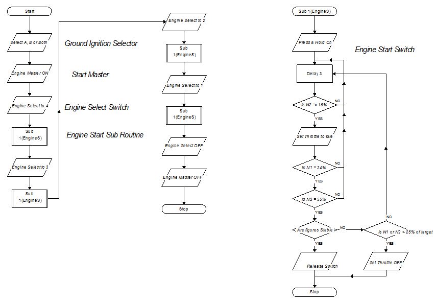
The Algorithm for the Engine Start Sequence. To start the engines on the BAe146 the
process is as follows:
1.
Set the GROUND
IGNITION SWITCH (top left on the Overhead Panel and not shown above) to one
of the following settings A, B or BOTH.
2.
Set the START
MASTER switch to ON.
3.
Rotate the START
SELECT knob to 4 (Engine No. 4).
4.
Press and hold the ENGINE STARTER switch to START.
5.
Watch the N2 gauge and when it reached 15% set THROTTLE 4 to IDLE.
6. If
N1 is equal to or Greater than 24% and N2 is equal to or greater than 55% and
Stable, release ENGINE START switch.
Switch is spring loaded and returns to run.
7.
(If N1 or
N2 goes more than 25% above their norm with the throttle set at idle set
throttle 4 to closed).
Repeat the process for the
remaining engines by rotating the start Select knob to engines 3, 2 and 1 in
turn and repeat steps 4 to 7 for each engine.
With all engines started set the ENGINE SELECT knob to OFF and the ENGINE
MASTER switch to OFF.
Program Flow Diagram. Below is the flow diagram for the engine start system. The sub-routine is repeated for each engine start sequence and goes through a process of determining whether the engine has started correctly or not, although this ultimately is a judgement made by the pilot based on the engine read-out of the N1 and N2 sensors on each engine.
Framing for the Panel. First of all, I drew up plans for the panel using SketchUp. Once again, this free on-line program proved priceless for making a full scale design plan for the build. This plan was then used to actual build the frame on top of it in a similar way that I used to build balsa wood models.


The actual frame was built using 3mm MDF cut into strips 60mm wide. This was actually a fairly straight forward task of cutting pieces to the right length and then gluing and stapling it together with 10mm blocks in each corner to strengthen and, ultimately to provide a point to screw the panels onto, Here's the frame in place in the overhead.

With the frame made the next task was to get onto making the actual panels.
Designing the Displays. I've pondered long and hard on this. As you saw from previous blogs I was looking at going commercial on this and having the display printed onto plastic once I had made the design using vector images. However, in the end I've used good old Microsoft Publisher to make the design and two pieces of perspex on either side to support it. May not be ideal, but at least it's homemade and cost effective. Basically, I found an image of the overhead and scaled it in Publisher to the required size. After that it was then a process of using the software tools to create the display. Overall I was pretty happy with the end result.
 |
| On the left the Publisher design with blue sections showing where switches go....and on the right the original image.
Working with Perspex. Mmm, not the easiest material to work with! You do need to be very careful with this material as it can shatter very easily - for example, drilling holes. If you go straight to the largest drill bit, it can catch on the perspex and crack or shatter it instantly. In my case I had lots of holes to drill - a small one in the corner of each rectangle where the rocker switches needed to go. I then took a larger drill piece to drill a pilot hole for the electric scroll saw. I didn't clamp the work down as there were lots of single holes to drill. In one case the drill caught, lifted the plastic and then dumped it again, and immediately caused it to shatter - lesson learnt. If you use a smaller drill bit and work up to the required size in stages it will save you a lot of heartache.

Here, drilling holes in the corner of each switch hole to be cut out.

I used my Dremel drill and new Dremel Moto scroll saw to cut and shape the holes - quite difficult to make the holes neat.

The engine start panel with the switches and knobs in place.
|
Monday 21 December 2015
Putting the Cockpit Windows In
It's been sometime since I last put up a post and that's simply because progress has been virtually at a stand still since the beginning of November when I fired up 'The Beast' for the first time and started loading software. Work has simply just kept me too busy to be able to spend any time building.
However, over the last couple of weeks I have been putting in the perspex windows. Perspex is a good material to use as it has good clarity and it's flexible which helps to provide a realistic curve to the windshields.
It's worth researching and reading up about how to work with Perspex - although it is flexible, it can split or shatter quite easily if you don't use the right tools to cut and drill it......as I found out. So this is what I did:
- To cut it, I used my renovator tool rather than a circular saw as this prevented the Perspex shattering.
 |
| The Renovator (left) is much more suitable for cutting the perspex compared to a circular saw |
 |
| Sorry if you're squeamish - lesson learnt! |
- Whatever you do, don't do what I did - last Saturday I was trying to cut Perspex with a craft knife - I couldn't be bothered going down to my workshop.......40 minutes down the road to the nearest medical centre open on a Saturday and 9 stitches later.
- Secondly, I thought it would be sensible to use a wood drill to drill a hole in perspex - wrong! All this did was crack the perspex, but thankfully in this case not in a place that would be in my face the whole time. I found the best way of drilling was to drill a pilot hole first with a metal drill and then re-drill with a bit of the right size - don't be tempted to drill at too high-a-speed, this could again cause cracking.

 |
| Use a metal drill bit (left) - not a wood one (right) |
- Make sure you drill the holes over-sized and use screws with large flat heads otherwise again you risk cracking the plastic. If you do crack the plastic, then take a small drill bit and drill a hole at the end of the crack - this will stop it extending further (actual practice used on aircraft cracks).
To provide a bit of realism I've added a foam lining to the windows to represent the rubber seals. Trying to buy something that would do the job was either impossible or ridiculously expensive, so I ended up cutting up an old foam camping mat (without managing to slice my finger ;-) ). You can see the lining in the photo with the crack.
Here are the windows all in place - I haven't stripped the protecting cover off completely yet until I'm certain I've finished all the construction on the outside. Also, you can see that where the Flight and Engine instrument monitors are I've covered these with MDF lined on the inner face with the plastic sheeting that came with the monitors to protect the screens - it will also help to keep the dust off when not in use.


Now, I have a question that I would love an answer to! On the centre pillar of the BAe 146's windshield there are two orange balls, mounted horizontally. I've simulated this using two widget balls out of a couple of cans of Guiness, but can anyone tell me what this device is? I suspect it's some sort of turn and balance device, but I could be completely wrong. I look forward to hearing from you.


Sunday 1 November 2015
PDC172 Comes Alive
Today has been a very significant day. Apart from the All Blacks winning the Rugby World Cup, it's also bee the day that I've fired up the Beast (the name of my Flight Sim computer) for the first time while it's connected to the data projectors and the monitors in the cockpit.


This is just a Cessna cockpit, but what it shows is that the interfacing is working, but there's a long way to go to get it fully up and running

To remind you, I've built a 180o curved screen and, although I've still got to get the position of the projectors right, this image shows that the principles are right. I will need to get warping software in order to get the perspective right on the screens....sadly this software is not cheap from what I can see - $400-500 - ouch!
Sunday 18 October 2015
Data Projection - Not Quite Right!
.......Oh well, attempt number one didn't work!
I had assumed that the image coming out of a data projector would be projected straight out from the projector, but that does not seem to be the case. I've got two Dell S320 that I bought in Singapore while we were on holiday there last year (Reason: I bought these through a retail shop in Singapore, it was so much cheaper than what Dell NZ could offer, even after trying to negotiate with them. In my view it's just not right that prices vary so much depending on the country you live in - ).
When I switch the projectors on with the projectors set to ceiling mounted, the image projected right down at the bottom of the screen. I looked for options through the menu to change this, but no joy......I took the whole set up down to try again.
What am I trying to do? Well, I'm now hoping to mount the projectors 'right-way-up' near the ceiling, but as these images show, with the short throw projectors, I've got them angled down at about 45 degrees and they are still not low enough! I've sent an email to Dell Technical Support to se if there is something I'm missing setting-wise.


If anyone knows or can help please feel free to comment.
I'm planning on making jigs similar to the ceiling mounted ones to try and solve the problem. As a start, I used SketchUp, once again, to help with getting the dimensions right - I really do recommend this as it has helped me on this project and others on many occasions.

Even now after remounting the projectors it's still not right, but it's much better - so it will have to be on trial and error until I get it right.
Sunday 16 August 2015
Mounting the Data Projectors
I'm using two Dell S320 short throw projectors for the scenery on the semi-circular screen. As the radius of the screens is 1.5m, these need to be angled downwards at angle of about 30 degrees. Most data projector ceiling mounts don't rotate that much, so I've had to devise my own system for doing this. With one piece of wood cut to an angle of 45 degrees to angle the projector to the right quadrant of the screen and the other to 30 degrees to point it downwards, I've been able construct a method to resolve this as the image below shows.


Having connected the mounts to the blocks of wood and the data projectors to the mounts I joined the two projectors together with a metre length of wood - this was simply to help with the mounting of the projectors on the gantry (temporarily clamped to the kitchen work bench). This image clearly shows the two angles 45 and 30 degrees.
 |
| Dell S320 Projectors mounted on their stands and the bar |
Finally the two projectors and the bar are mounted on the gantry - hopefully my measurements and calculations will be about right.
 |
| In position on the gantry - the screen behind |
The next step will be to power them up and make some basic adjustments before connecting everything else up...........
Friday 24 July 2015
'The Beast'' is Created
The Components. With the main components delivered, I went and bought the case, a 1000W PSU and a couple of extra cooling fans last weekend. So this week has been spend building the Beast. I'll be making a video that chronicles the build when I have time, but in the meantime here is a photo-diary highlighting some of the key events and issues. It's got to be pretty grunty so I've gone for an Intel i7 processor, the GTX 980 graphics card, an SSD drive and 16Gb of RAM all mounted on an ASUS Sabertooth Z97 motherboard.

 M/B Cooling Fans. The first step is to set up the motherboard. This is best done before it's mounted into the case. The Z97 comes with what ASUS calls a Tuf case that protects key components from dust and accidental damage. It also comes with a couple of extra cooling fans that blow cooling air underneath this Tuf cover, but these need to be installed by the buyer.
What the Forums Say! There is some debate on various forums whether these fans are needed, but in my view it is best to install them as this can only help with cooling - some people are suggesting the fans are noisy, but having carried out a test start on my machine there was nothing untoward. Also as this will be driving Flight Sim there's going to be jet noise anyway so an extra fan or two making a bit of noise won't make much difference ;-)
 Installing the Processor. The processor is also best installed before you mount the motherboard in the case - space becomes a bit more restricted once the motherboard is installed. This is pretty straightforward. There is a blank on the head of the processor bay which the instructions say MUST NOT be removed until after the processor is installed - not really sure why other then to protect the mounting position. To install, lift the spring lever and carefully place the processor onto it's mount. Look carefully at both the processor and the mount beforehand to check which way round it goes. Depending on the processor you are using, you will find either one corner blanked or in the case of the Intel i7 there are two notches positioned on the side of the chip that correspond with two ridges on the mount. Once in position carefully lower the spring clip and lock it in position. As you do so the blank will pop off.
 RAM. I'm initially installing 16Gb of Corsair Vengeance Pro 16GB which comes in 2 sticks of 8Gb. The instructions specify that these are installed into specific ports. The number of sticks being put in determines the ports that they go into. I found it easiest to install the RAM before installing the motherboard, but in reality it doesn't matter which way round you do it - the only thing to remember is that once the motherboard is installed, access and light becomes more restricted.
Cooling Fans. As there is a possibility that I might be overclocking this beast I decided that I would add a couple of additional fans to the case and a larger cooling fan for the processor. I originally tried mounting the case fans to extract air out the top, but having put the the motherboard in (next paragraph) there just wasn't enough space for everything. I took one out from the top and placed it in the base to suck cool air in. (note: because of the size of the CPU fan I installed this after I had installed the motherboard - again, a matter of preference).
Installing the Motherboard. When you're ready, prepare case by taking off the side panel(s). These are usually held in place with a couple of small screws at the back and then once removed, the panels can be slide back a couple of centimeters and lifted off. Inside the case you should find a box or bag with all the screws and accessories needed to install the motherboard and drives. Make sure to connect the earthing cable and the check the stand-offs match the screw holes on your motherboard.


 |
| 40mm cooling fan mounted on the I/O ports |
Following the Instructions. Following the instructions that come with the motherboard makes installation pretty straight forward. The only area where I was a little uncertain was the connection of the case cooling fans (explained later). I also wasn't too certain about the placing of the thermistor sensors (again, more later). Don't forget to use an earthing mat and wrist strap to discharge any static charge.
 Installing the Processor. The processor is also best installed before you mount the motherboard in the case - space becomes a bit more restricted once the motherboard is installed. This is pretty straightforward. There is a blank on the head of the processor bay which the instructions say MUST NOT be removed until after the processor is installed - not really sure why other then to protect the mounting position. To install, lift the spring lever and carefully place the processor onto it's mount. Look carefully at both the processor and the mount beforehand to check which way round it goes. Depending on the processor you are using, you will find either one corner blanked or in the case of the Intel i7 there are two notches positioned on the side of the chip that correspond with two ridges on the mount. Once in position carefully lower the spring clip and lock it in position. As you do so the blank will pop off.RAM. I'm initially installing 16Gb of Corsair Vengeance Pro 16GB which comes in 2 sticks of 8Gb. The instructions specify that these are installed into specific ports. The number of sticks being put in determines the ports that they go into. I found it easiest to install the RAM before installing the motherboard, but in reality it doesn't matter which way round you do it - the only thing to remember is that once the motherboard is installed, access and light becomes more restricted.
 |
| CPU Cooling Fan and the RAM |
Installing the Motherboard. When you're ready, prepare case by taking off the side panel(s). These are usually held in place with a couple of small screws at the back and then once removed, the panels can be slide back a couple of centimeters and lifted off. Inside the case you should find a box or bag with all the screws and accessories needed to install the motherboard and drives. Make sure to connect the earthing cable and the check the stand-offs match the screw holes on your motherboard.

Before you install the motherboard remember to clip in the backing plate for the I/O ports. Carefully place the motherboard into position by partly rotating it placing the I/Os in place first and then lowering onto the standoffs so that the screw holes line up. Screw the motherboard in place by first putting one screw in but not tightening it and then screw the rest in taking care not to over tighten them.
Installing the Rest. Once the motherboard is in place, it just a matter of following the instructions to install the rest of the components and connect the various leads. As well as the instruction booklet for each part and the motherboard booklet, there are also numerous YouTube videos that you can follow - my recommendation is to not just look at one, but check out several in order to get the full picture. The components include the SSD, the DVD R/W drive and finally the GeForce GTX 980 Graphics card. All of this was straight forward and relatively simple. The only areas that proved a challenge - not forgetting that this is the first PC I'm building from scratch - was the connection points for the numerous fans and the power connections for the graphics card - the instructions were a little vague and so needed extra research, but in the end again, was relatively straight forward.
Tidying Up the Case. Having got everything in place and wired up, the next thing is to tidy up the wiring making sure it's kept clear of sensitive parts. The good thing with the Sabertooth motherboard is it has holes for you to feed the cabling through to the back to keep it out of the way. Grouping the cables together and strategic use of ties works well. This is what the final installation looks like.
 |
| Motherboard without the I/O cover in place |
Installing the Rest. Once the motherboard is in place, it just a matter of following the instructions to install the rest of the components and connect the various leads. As well as the instruction booklet for each part and the motherboard booklet, there are also numerous YouTube videos that you can follow - my recommendation is to not just look at one, but check out several in order to get the full picture. The components include the SSD, the DVD R/W drive and finally the GeForce GTX 980 Graphics card. All of this was straight forward and relatively simple. The only areas that proved a challenge - not forgetting that this is the first PC I'm building from scratch - was the connection points for the numerous fans and the power connections for the graphics card - the instructions were a little vague and so needed extra research, but in the end again, was relatively straight forward.
Tidying Up the Case. Having got everything in place and wired up, the next thing is to tidy up the wiring making sure it's kept clear of sensitive parts. The good thing with the Sabertooth motherboard is it has holes for you to feed the cabling through to the back to keep it out of the way. Grouping the cables together and strategic use of ties works well. This is what the final installation looks like.
 |
| The front................ |
 |
| ..............and the back |
Subscribe to:
Posts (Atom)