The Overhead Panel. Once again it's been a loooong time since my last post - too much work getting in the way of play, unfortunately. Part of the flight deck
comprises the overhead panel which includes a number of different systems, one
of which is the engine start system. This will be the first of 11 panels that
will need to be built in order to complete the overheard panel.

Curriculum Learning. By the way, I'm a teacher now and at my school we've recently introduced a project day for students where they can get involved in something they are passionate about, so part of this is to show how their learning links to the curriculum. As an example, throughout the course of this
project I will be learning to work with plastics as a hard material, learn
programming and electronics. This means that I will be covering the following
curriculum areas:
·
Literacy – writing reports covering the
development and progress of the project
·
Maths – calculating voltages, currents and power
requirements for electrical circuits.
Costings for components and calculating measurements and quantities.
·
Computer Science – programming circuits to
control inputs and interface with computer programs.
·
Electronic Technology – designing and building
electronic circuits to enable the actual functioning of switches and dials.
·
Graphic Design - designing the panel’s physical
interface.
Purpose. The purpose of this
project is to design and build the engine start system to include appropriate switches
and indicator warning lights, and to interface this with Flight Simulator.
Construction. The overhead panel frame
will be constructed using a wooden frame for each section and a double layer of
Perspex with a printed display in between to enable the panel to be back-lit.
Switches will be commercially bought to closely match those in the aircraft,
but some compromise will be required. Dials will inevitably need to be built
from scratch. All systems will be backed
with electronic components connected to Arduino circuit boards that provide the
interface with Flight Sim.
Engine Start System Requirements. The system will require
the following switches as shown in the diagram below. Furthermore, it will be necessary to design
and build the required electronic components to interface with an Arduino
system which in turn is programmed to interface with the flight simulator
program through another program called Flight Simulator Universal Inter-Process
Communication (FSUIPC) – I’ve always looked at as being the Flight Simulator
User Interface Program Controller.

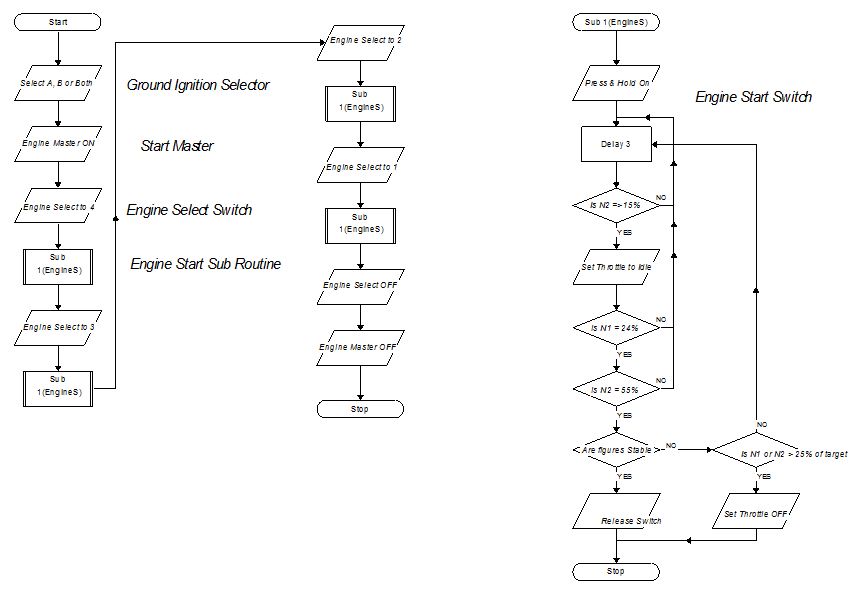
The Algorithm for the Engine Start Sequence. To start the engines on the BAe146 the
process is as follows:
1.
Set the GROUND
IGNITION SWITCH (top left on the Overhead Panel and not shown above) to one
of the following settings A, B or BOTH.
2.
Set the START
MASTER switch to ON.
3.
Rotate the START
SELECT knob to 4 (Engine No. 4).
4.
Press and hold the ENGINE STARTER switch to START.
5.
Watch the N2 gauge and when it reached 15% set THROTTLE 4 to IDLE.
6. If
N1 is equal to or Greater than 24% and N2 is equal to or greater than 55% and
Stable, release ENGINE START switch.
Switch is spring loaded and returns to run.
7.
(If N1 or
N2 goes more than 25% above their norm with the throttle set at idle set
throttle 4 to closed).
Repeat the process for the
remaining engines by rotating the start Select knob to engines 3, 2 and 1 in
turn and repeat steps 4 to 7 for each engine.
With all engines started set the ENGINE SELECT knob to OFF and the ENGINE
MASTER switch to OFF.
Program Flow Diagram. Below is the flow diagram for the engine start system. The sub-routine is repeated for each engine start sequence and goes through a process of determining whether the engine has started correctly or not, although this ultimately is a judgement made by the pilot based on the engine read-out of the N1 and N2 sensors on each engine.
Framing for the Panel. First of all, I drew up plans for the panel using SketchUp. Once again, this free on-line program proved priceless for making a full scale design plan for the build. This plan was then used to actual build the frame on top of it in a similar way that I used to build balsa wood models.


The actual frame was built using 3mm MDF cut into strips 60mm wide. This was actually a fairly straight forward task of cutting pieces to the right length and then gluing and stapling it together with 10mm blocks in each corner to strengthen and, ultimately to provide a point to screw the panels onto, Here's the frame in place in the overhead.

With the frame made the next task was to get onto making the actual panels.
Designing the Displays. I've pondered long and hard on this. As you saw from previous blogs I was looking at going commercial on this and having the display printed onto plastic once I had made the design using vector images. However, in the end I've used good old Microsoft Publisher to make the design and two pieces of perspex on either side to support it. May not be ideal, but at least it's homemade and cost effective. Basically, I found an image of the overhead and scaled it in Publisher to the required size. After that it was then a process of using the software tools to create the display. Overall I was pretty happy with the end result.
 |
| On the left the Publisher design with blue sections showing where switches go....and on the right the original image.
Working with Perspex. Mmm, not the easiest material to work with! You do need to be very careful with this material as it can shatter very easily - for example, drilling holes. If you go straight to the largest drill bit, it can catch on the perspex and crack or shatter it instantly. In my case I had lots of holes to drill - a small one in the corner of each rectangle where the rocker switches needed to go. I then took a larger drill piece to drill a pilot hole for the electric scroll saw. I didn't clamp the work down as there were lots of single holes to drill. In one case the drill caught, lifted the plastic and then dumped it again, and immediately caused it to shatter - lesson learnt. If you use a smaller drill bit and work up to the required size in stages it will save you a lot of heartache.

Here, drilling holes in the corner of each switch hole to be cut out.

I used my Dremel drill and new Dremel Moto scroll saw to cut and shape the holes - quite difficult to make the holes neat.

The engine start panel with the switches and knobs in place.
|