Saturday, 11 April 2015

Lining the inside

Having put the lining in the cockpit window frames over the last couple of days,  today's task has been to 'fill in'  the gaps inside the cockpit - looks a bit untidy at the moment, but with filler, sanding and painting it will all look awesome.

Again, using hot water enabled me to bend the corner sections on the top an bottom of each window mullion to fit the curve of the cockpit.

Thursday, 9 April 2015

Cockpit Windows - Bending the wood

High flying airliners don't have right angled (or sharp angled) corners as these become weak spots from which cracks can develop.  Aviation enthusiasts might remember this was the cause of the de Havilland  Comet crashes in the 50s. Ever since then all jet airliner windows have curved corners.

Sharp angled corner....
I've started working on the putting the curves onto my cockpit windows.  Early tests using thin wood or MDF showed  that you could only bend it so far before the wood or MDF snapped.  One thing I know is that wood can be bent more easily if it is wetted, so having measured where I needed to make a bend I placed the 3mm MDF strip I'm using for the lining in a basin of hot water.  Whilst submerged I flexed the strip in the direction I wanted the curve to follow.  As you work it, you can feel it becoming more flexible and after about 30 seconds it is ready for taking out and inserting into the frame.

........rounded of using MDF 
The pencil marks you see help to identify the area that needs to be immersed in water and the extend of the bend

I've made a short video that shows how I went about bending the MDF and fitting it to the frame:

Eating Humble Pie

Ok, my post from yesterday might have been (was) a bit premature.  I woke up this morning and thought I would give the paint another chance.  I made sure I stirred it thoroughly with a stronger piece of wood and sure enough I could feel the resistance at the bottom of the pot. Over the day I gave the screen 3 more coats and I'm now pretty pleased with how it's looking

......my apologies to Spring Paint

Wednesday, 8 April 2015

You don't always get it right

Having erected my screen and filled and smoothed the cracks with jointing compound, I've ended up with a nice smooth semicircular screen.  I started to paint it this evening with undercoat bought at our local DIY store in Christchurch - it was, I thought, good value.  However, the result of the first coat going onto MDF looks very disappointing
I'm going to give it another coat in the hope that it was just the first coat soaking in and sealing, but I've got my doubts.  The answer is don't buy cheap, I suppose?
Cheap Paint! :-(
On a more positive note:  I emailed a well-known paint supplier in New Zealand and Australia, Resene, to find out if there is a special paint that can be used to provide a good reflective projector screen and it appears there is.  This is the information I've received back: "Apply a coat of Resene Quick Dry Primer Undercoat to the bare MDF then apply 2 coats of Resene Spacecote Flat tinted to Resene Silver Sand N80-006-102." - Courtesy of Resene Paints (http://www.resene.co.nz/)
Screen paint swatches - Need to check which shade the email refers to

Sunday, 5 April 2015

Instrument Panels and Display Screens

Using Adobe Fireworks has enabled me to create a vector diagram to create the panels that will then be converted  to a pdf and taken to a signmaker to print onto plastic.  Before I go the whole hog though I will talk with then and also ask for  sample so that I can see that it meets my spec.


On this image the yellow sections represent areas that will need to be cut out for switches and dials, the red section with the black background and orange text also needs to be cut out for annunciator panels, and the blue circles are where screw holes will be.

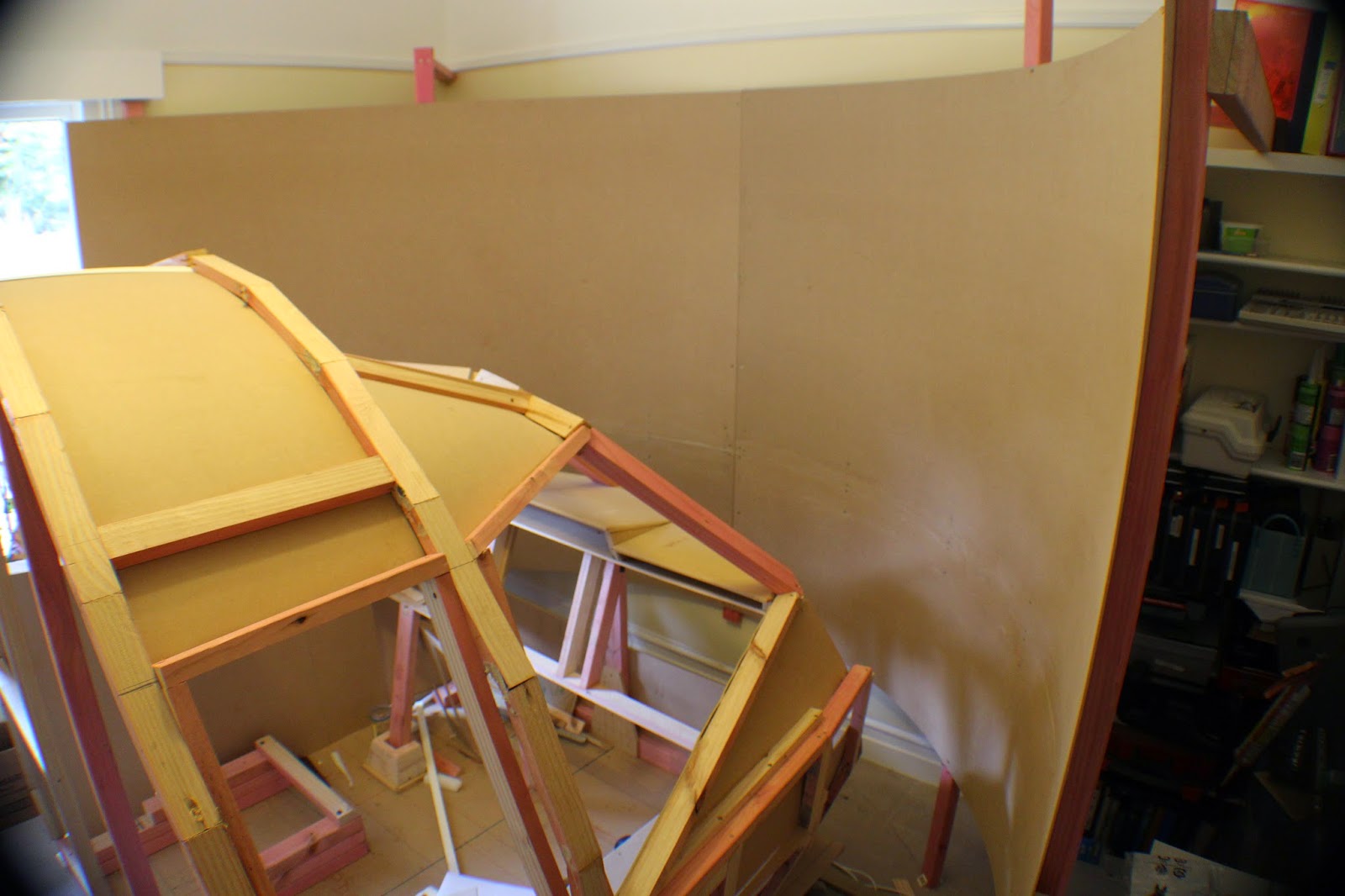
I've also made a start on the semicircular screen.  this is made from sheets of 3mm MDF.  I started by joining a board and a half (cut lengthways) to make each half of the screen - in other words each half measures 2.4m wide by 1.8m high.  The important part of joining the boards is to make the joins as invisible as possible.
 I used 6 blocks of MDF to strengthen the joint and glued and screwed these to the sheets making sure the heads of the screws are counter-sunk.
I also used adhesive paste to hold the pieces together and to help make the joints more invisible.
The first half mounted - you can still see the joint, but through a combination of plastering, sanding and painting this should become virtually invisible.

Another day and the second half of the screen is up.  Both halves follow the original line that I scribed out on the carpet right at the beginning.

One challenge was to get the centre joint to be as flat as possible in relation to each other so that there was no obvious crease.
Taken with a wide angle lens so it's difficult to see the 180 deg. curve of the screen.

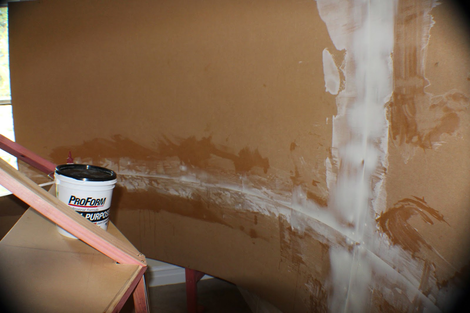
The next step is to use some jointing compound to fill cracks and smooth out any unevenness before painting it.

The joints and screw holes evened out with jointing compound
Depending on how it goes, I might give it a second coat, but I will sand it down first.

Thursday, 2 April 2015

Panel Visuals - Creating Digital files


At the same time as researching and working on the the spec for the computer, I've also made a start on the visuals for the instrument panels.  These panels will need to look good both during the day and at night.  I'm aiming to make these back lit to match the real displays as this image show.

I'm starting with the overhead panel so I measured the space on my build where this panel will go. I then found an image of the overhead panel and imported it into Adobe Fireworks ensuring it's width matched the space I have available on my flightdeck.  The reason for this is that this program has the option to create a vector image.  (To understand more about the difference between a vector image and a bitmap/jpg click on this link here) Vector and Raster images
If you don't have a program that creates vector images you can always use a program like Microsoft Publisher that you can still draw objects of various shapes and sizes and also edit text.

Having imported the image, it just a question of using the tools within the program to create the overlay - the images below help to show what I mean.

Showing the start of marking the overlay on the original background image
Still a work in progress, but here showing the template with background colour added

This 2 minute video show the method for overlaying the image and placing text

In addition to starting work on the panels, I've also been looking into how I can print these.  Clear plastic PVC is probably the obvious answer and because they need to be high quality I've looked into a few local companies that do sign making. I've been quoted about NZ$160/sq.m. which I think is quite reasonably if it achieves the result I want.

Tuesday, 31 March 2015

Computer Specification

It's been a wee while since I've been able to do any work on the build of my project, but what I have been doing is researching components for the build of the computer that will power my simulator.

When researching, it's important not to just base it on the first site you come to, but consider a few. So far, I've found a couple of really useful websites - one is a specialist provider of flight sim computers - Jetline Systems - and the other is  a site that provides really useful information to people wishing to build their own gaming machine - Elite Gaming Computers (EGC) - who provide impartial advice on building a gaming computer of any spec - cheap to top end. Here are the sites:

Jetline Systems - http://jetlinesystems.com/performance.php
Elite Gaming Computers - http://elitegamingcomputers.com/ 

I'm still working of the exact spec for the build, but this is where I'm heading and shows the savings that can be made by shopping around:

Parts Component US$ Converted  to NZ$ Price in NZ
CPU Intel i7 4790k $335.00 $445.55 $489.00
Graphic Card Gigabyte GeForce GTX 980 $549.00 $730.17 $846.00
Memory Corsair DOMINATOR Platinum Series 16GB (2 x 8GB) DDR3 DRAM 2400MHz  $280.00 $372.40 $399.00
Motherboard ASUS SABERTOOTH Z97 MARK1 $249.00 $331.17 $391.00
Hard Drive Crucial M500 960GB SATA 2.5-Inch 7mm (with 9.5mm adapter) Internal Solid State Drive CT960M500SSD1 $378.00 $502.74 $668.64
PSU LEPA G Series 1600W 80PLUS Gold Full Modular PSU $257.00 $341.81 $475.00
Case full size coolmaster $244.00 $324.52 $325.00
Total $2,292.00 $3,048.36 $3,593.64

Saturday, 28 February 2015

Research and Testing

It started with research into electronics and programming to interface analogue switches with FSX.

There are many solutions out there and my research found that there were many different methods to solve a problem.

Here are a couple of short videos I made during my research to give you an idea of where I'm going.

First - simple electroniques - making LEDs flash
The second short video shows hardware interfacing with FSX to simply make the landing gear go up and down.  Having learnt how to do that helps to demonstrate the rest should be possible...fingers crossed

Friday, 27 February 2015

Marking Out and Laying the Base

After identifying a space for my project (a spare downstairs room), I marked out on the carpet the radius for the semi-circular screen  - I'm working on 1.5m radius with a view to using two short throw Dell projectors that at this distance can project to a screen width of just under 2.4m.  The idea is to use two 2.4x1.2m 3mm sheets of MDF to create the screen - bends beautifully and is quite light.
I then started building the base and marked the centre line - keeping an eye on the centre line, both on the base and as you build up in 3D is crucial to ensure that everything is balanced and central.
I've built the base on spring with a view to using a Butt Kicker to provide that sense of motion - ie turbulence and the rumble on the runway and taxiing etc. I've used 6 springs from old computer chairs.  These are heavy duty and certainly support my weight and  the weight of the structure pluse passenger.
The Butt Kicker
The great thing about this project is that it is involves using a wide variety of different skills.  To start with there is the wood working, but also in order to embed precision into the project, I've use Google SketchUp to produce a detailed drawing from which I can get accurate measurements.  This was particularly important with the curves of the 'fuselage'.

The drawings then helped with the cutting and building of the fuselage sections.


From here on its been a case of carefully measuring and cutting to build the structure up to something that looks like a flight deck....as I said earlier it's going to be loosely based on the BAe 146.  The seats I basically got free  (old car seats that I got for a box of 'good will' stubbies - good deal).

As mentioned earlier, making sure you keep and eye on where the centre line is, is vital.  It takes a bit of ingenuity (and a plumb line) to keep track of it as you work your way up :-)
 Here I've started work on putting in where the cockpit windows will go - and I'm using full sized cardboard cut outs to show the position of all the various panels.
The carpentry work is almost done now and I've started using 3mm MDF to close in the frame.  The next stage will be to paint the inside.


Tuesday, 28 October 2014

Introduction to my Flight Sim Home Build Project - BAe 146

My background - basically I'm a frustrated pilot.  I used fly helicopters and have a total of 560 hrs real flying time, but now I'm getting on a bit age wise and my hearing and eyesight aren't up to scratch anymore so I get my flying thrills through Flight Sim.  I've gone through the various versions of Microsoft Flight Sim since the 90's and like most simmers I've always strived for ultimate reality.

To begin with it was single screen, no internet and poor graphics, but as time went by and MS updated its program, so too did the quest for reality sink deeper under my skin.  Now I'm running FSX with a reasonably high spec computer and three, 23" screens using the internet and VATSim to get "as near as" reality as I can, flying the Just Flight BAe 146. 

But it's still not enough!

So after about 18 months of research and practice, I've taken to plunge and I've started building my own flight sim flight deck based on the legendary BAe 146/Avro RJ85.

Over the next few months (maybe years!) I'll aim to give you a detailed journal of my progress so that those of you like-wise inclined can follow this blog, learn from my mistakes and build your own flight deck.

It won't be to scale and it won't be the real thing (at least not to begin with), but at least it will be affordable, unlike the 737 modules and components that are available at hundreds/thousands of dollars.  What's more, doing it this way has created a hobby in itself, with the research, acquisition of knowledge and training to create the the programs to run the various modules....not to mention the electronics skills.

Hope you enjoy?